DIY: Diagnose It Yourself
* Warning: All information contained herein are for reference purposes only. If you do not feel comfortable working with the vehicle, it is highly-recommended that you use a well-qualified professional mechanic/technician to perform any work on the vehicle. JaguarClimateControl.com is not responsible for any damage or problems caused by use or misuse of this information.
If you suspect that your 1999-2008 Jaguar S-Type may have a damaged/defective:
Air Conditioning Climate Control Module (CCM)
also known as: “AC Control Unit”, “Dual Automatic Climate Control (DATC)”
and/or
Dual Coolant Control Valve (DCCV)
also known as: “Heater Valve”, “Dual Coolant Flow Valve”
…here are some guidelines and solution(s) that will help you Diagnose It Yourself.
* Some of the above terms may be used interchangeably throughout this website.
Quick Links:
Symptoms
Possible causes
Why the Heater Valve can become damaged
Overview of normal Heater Valve operation
Why the Climate Control Module can become damaged
Climate Control Module versions
How to diagnose
- Evaporator Temperature Sensors
Heater Valve and Climate Control Module electrical test procedure
- Test Procedure A
- Test Procedure B (highly recommended!)
Other symptoms
What JaguarClimateControl.com can do for you
Symptom(s):
Driver and/or passenger vent(s) blow(s) hot/warm air only, even when the controls are set to max cold “Lo” (or any other level). This may occur on just the driver side, just the passenger side, or both sides. It may be intermittent.
Possible causes:
1. Fault in the pressurized A/C system, including the compressor, condenser fan, refrigerant pressures, refrigerant leakage, etc.
2. Heater Valve is defective. After some time (approximately 3-8 years), corrosion and vibrations cause this component to fail either mechanically and/or electrically (i.e. water leakage, internal short circuit, etc.).
3. Climate Control Module is defective. When the Heater Valve becomes faulty, it begins to draw too much current, which causes the Climate Control Module to become damaged (i.e. failure due to over-current condition).
4. Harness/wiring problems between the Heater Valve and Climate Control Module.
5. Failure at one or more air mixing/blending flaps.
6. Or a combination of the above cases.
Why the Heater Valve can become damaged:
1. Corrosion – not enough anti-corrosion additive in the coolant.
2. Coolant leakage onto its electrical connections.
3. Vibrations, old age, etc.
Overview of normal Heater Valve operation:
Center pin to the DCCV supplies constant +12 to 14v power (straight from the fuse box). It is an active low circuit, so when the DCCV sees Ground at either the LH and/or RH pin, the respective solenoid within the DCCV activates.
Case 1: Temperature setting “Lo” = CCM output ON (grounded) = solenoid ENERGZIED = solenoid valve CLOSED = coolant flow to heater core impeded = heater core NOT HOT when A/C is ON.
Case 2: Temperature setting “Hi” = CCM output OFF (open circuit) = solenoid NOT ENERGIZED = solenoid valve OPEN = coolant flow to heater core allowed = heater core HOT when A/C is ON and coolant is HOT.
Case 3: Temperature setting “xx degrees, between Lo and Hi” = CCM output cycles ON/OFF = solenoid cycles ON/OFF = solenoid valve OPENING/CLOSING = coolant flow to heater core partially allowed/impeded = heater core somewhere between HOT / NOT HOT when A/C is ON.
Notes:
- Even if the CCM is turned off by the user, a non-damaged CCM will continually supply the Ground signal to the DCCV so that the heater core doesn’t continue to heat up the ambient air.
- There is an audible click sound when the DCCV solenoid is energized.
Here’s a picture of a faulty Heater Valve that was removed from a 2005 S-Type. Both of its solenoids were drawing too much current (one of which was tested at over 6 amps, an 850% over-current condition!):
 (a.k.a. heater valve) 02")
Why the Climate Control Module can become damaged:
There is no over-current fault-protection circuitry that protects it against damage due to faulty Heater Valve. This applies to S-Types from (late 2002) through 2008. The 1999 – (early 2002) modules, though still susceptible to damage, have a more robust design that reduces the chance of said damage.
Climate Control Module versions:
For 2003-2008 models, there are three (3) versions of the module. In cars without navigation, the CCM is part of the Climate Control Assembly. Cars equipped with navigation use a Remote Climate Control Module (RCCM). The RCCM is hidden behind the glovebox. Both modules are very similar electrically. They are, however, different enough that a nav version cannot be substituted for a non-nav version (unless the whole nav system is swapped in as well), and vice versa.
Here’s a picture of a 2003-2008 S-Type Climate Control Assembly, non-navigation version (CCM is built-in):
, non-nav")
The non-nav unit comes either with or without a front defroster (a.k.a. “front heated windscreen”) button:

Here’s a picture of a 2003-2008 S-Type Remote Climate Control Module (RCCM), found in navigation-equipped cars:
, nav-equipped 01")
Do not confuse the navigation head unit for the CCM or RCCM:

How to diagnose:
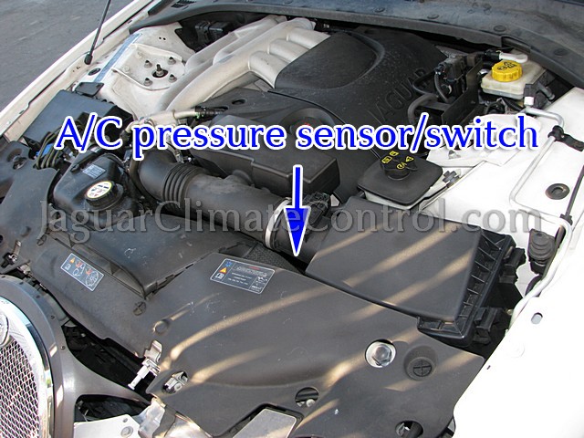
1. Check operation of the pressured A/C system, including 134a pressures, leakage, compressor operation, churning/grinding/rattling/buzzing noises at compressor, condenser fan operation, evaporator water drainage, etc.
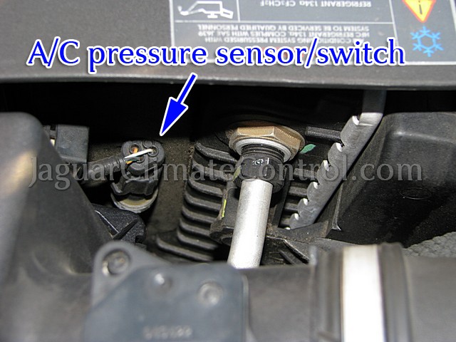
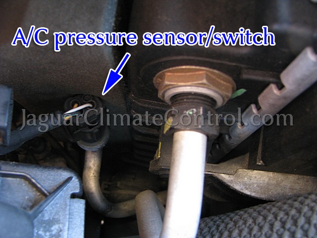
A/C pressure sensor/switch:
A/C low-side fitting:


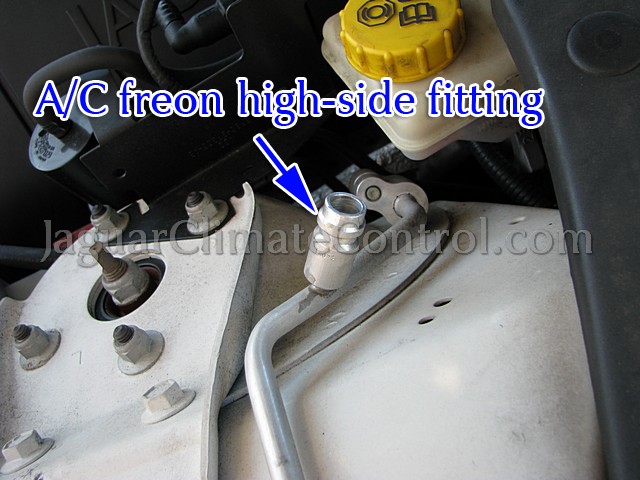
A/C high-side fitting:

2. Check the fuse for the Heater Valve. It is Fuse 32 (10 amps) in the Front Power Distribution Fuse Box, located in the engine compartment. This fuse is hot +12 volts at all times, and also feeds the Auxiliary Coolant Pump Relay (4.0L models) and A/C Clutch Relay.

3. Check the connection to the Heater Valve. It is immediately behind the radiator, on the passenger-side, and buried deep down below the coolant expansion tank and some hoses. Are the connectors secure? Is there any sign of corrosion in the connector terminals? Is the Heater Valve corroded?
 Location")
4. Check the Evaporator Discharge Temperature sensor(s) located under the dash. On the 03-08 S-Type, there is one (1) sensor at the passenger side, and two (2) sensors at the the driver side, all attached to the Evaporator housing under the dash, just above the transmission tunnel. Measure the resistance of each sensor. If one sensor measures very different from the other two sensors, then it’s time to replace that sensor.
Driver side:


Passenger side:


These temperature sensors are basically just thermistors that vary in resistance as the temperature changes. All three (3) sensors are identical, and should behave the same way and show similar resistance readings when compared side-by-side. If the comparison shows one sensor to be very different, replace that sensor. Together with the Climate Control Module, these sensors help to prevent freezing (0 degrees C or below) of the moisture on the evaporator coil.
5. Perform the Heater Valve test procedure outlined below.
Heater Valve and Climate Control Module electrical test procedure:
Overview:
The purpose of this electrical test is to help us determine if the Heater Valve is receiving the necessary signals required for basic operation, and to give us a general idea of the health of the Heater Valve itself. We can also pre-determine (with 80% certainty) if the Climate Control Module is damaged or not. The same test can be performed on all model years of the S-Type, 1999-2008.
Here is a visual reference for the contacts (Heater Valve side) you will be taking measurements at. The plug (harness side), though not illustrated, is basically just the mating connector to this:
 (a.k.a. heater valve) 01")
Pin 1 is for for driver-side control.
Pin 3 is for for passenger-side control.
Necessary tools:
- Digital multimeter (to measure voltage, current, and resistance).
- Insulated test leads/wires with alligator clip ends (to clip onto male contacts or stripped wire ends).
- Insulated wires, stripped on both ends (to get access to hard-to-reach female contacts in the plug).
- Socket set, with 12″ (minimum) extension.
- Temperature sensor tool/gun (to measure temperatures at the air vents and/or heater hoses, optional).
- Digital clamp-on DC ammeter w/ mA to 10A range (to simplify the current measurements, optional).
Get access to the Heater Valve:
The Heater Valve is located on the passenger-side just behind the radiator. On 03-08 S-Types, look for 3 attached water hoses. 99-02 models have 5 attached hoses.
1. Unbolt the Coolant/Water Expansion Tank, set it aside so it doesn’t block access to the Heater Valve.
2. Loosen the bolt that secures the Heater Valve to the car.
3. Rotate the Heater Valve to get access to its connector.
Procedure A (This one is messy. We recommend that you do Procedure B instead.):
1. Run the engine for 5 minutes to warm up the engine coolant.
2. Set the temperature controls to max “Lo” for both driver and passenger sides.
3. Confirm that the air is still blowing hot or warm (take note which vents blow hot/warm).
4. Check for heat in the inlet and outlet hoses attached to the heater valve. Use a temperature sensor tool/gun or carefully use your hand to feel which hoses are hot or not hot.
5. Disconnect the plug from the Heater Valve and take voltage measurements at only the inner contact in the plug (harness side). It should read 14v or so (during engine operation), since this connection goes straight to Fuse 32 (10A) in the Front Power Distribution Fuse Box.
 Location")
 Location")
6. Take resistance measurements at the 2 outer contacts in the plug (measure between each contact and a chassis ground). Each should read close to 0 ohms, because each Heater Valve solenoid needs to see a Ground “signal” in order to activate. You can call this a “continuity check.”
7. Jumper the plug’s inner contact to the Heater Valve’s inner contact so that the Heater Valve can get 12v power.
8. Jumper one outer contact in the plug to the corresponding outer contact at the Heater Valve while using the multimeter in series to measure current. Be careful that you don’t short anything with the inner contact connection, or you will see sparks and blow Fuse 32.
9. Repeat the measurement at the other set of outer contacts after disconnecting the first set of outer contacts (don’t disconnect the inner contact connection yet). Each measurement should read 0.6 to 0.9 amps. A higher value indicates over-current fault in the Heater Valve solenoid.
10. With the inner contacts still jumpered between the plug and Heater Valve, jumper an outer contact on the Heater Valve to a chassis ground, while using the multimeter in series to measure current. Check to see if any vents blow cooler air during this grounding process. Repeat the measurement at the other outer contact and check the vents again.
11. Shut off the engine.
12. Report the results.
Procedure B:
If you have a clamp-on DC ammeter and temperature sensor gun, this test is much easier/quicker to perform. It is our abridged-version of Jaguar’s Technical Service Bulletin (TSB), number JTB00103, dated June 13, 2008, applicable to S-Type (X200) VIN: L00600 through N91220, model years 2000-2008. If you read the TSB, you’ll see that it specifies the use of a Midtronics PSC-550 Vehicle Power Supply, but it’s basically just being used as a clamp-on DC ammeter anyway. Depending on the results of Procedure B, the more difficult Procedure A may still need to be performed.
For your convenience, we have created a convenient Test Sheet for you to print out and fill in during your testing. You can download it here:
PDF format: Procedure B Test Sheet Rev. -
PNG format:

(If you don’t have a mini clamp-on ammeter, you can still perform Procedure B by using your regular multimeter to complete only section ii. on the test sheet)
1. Run the engine for 5 minutes to warm up the engine coolant.
2. Set the temperature controls to max “Lo” for both driver and passenger sides, and wait 5 more minutes.
3. Confirm that the air is still blowing hot or warm (take note which vents blow hot/warm).
4. Record the driver, center, and passenger vent temperatures. Record measurements onto the Procedure B Test Sheet. Each should measure 7 degrees C (45 degrees F). If either vent temperature is greater than 45 degrees F, or the difference between each side is greater than 6 degrees C (10 degrees F), continue to the next step.
5. Remove the left-hand fascia end-panel.
6. Measure the voltage, resistance, and/or current using a clamp-on ammeter or standard multimeter (see test sheet for further details) at the brown/green (NG; FC-11) wire, then at the brown/blue (NU;FC5-12) wire at connector FC5. Applies to VIN L00600 – M45254 only (presumably for the 1999-2002 model years). Record measurements onto the Procedure B Test Sheet:

or Measure the voltage, resistance, and/or current at the brown/green (NG; FC4-9) wire, then at the brown/white (NW; FC4-10) wire at connector FC4. Applies to VIN M45255 – N91220 only (presumably for the 2003-2008 model years). Record measurements onto the Procedure B Test Sheet:


Each current measurement (using a clamp-on ammeter) should read 0.6 to 0.9 amps. Any higher value indicates over-current fault in the Heater Valve solenoid, and the Climate Control Module will become faulty in the near future. A value of 0 amps indicates fault at either the Heater Valve and/or Climate Control Module.
7. [Optional] Set the temperature controls to max “Hi” for both driver and passenger sides, then repeat all measurements again.
8. Shut off the engine.
9. Report the results.
Other symptoms:
If your A/C blows cold air on the LO setting and hot air on the HI setting, but has problems with in-between temperature settings, then pay extra attention to these notes:
Symptom #1: Air either blows hot or cold only. When the temperature is set to 66 deg. F or below, the air blows full cold. When set to 67 deg. F or higher, the air blows full hot, regardless of ambient temperature.
(These temperature numbers are used as examples only. You may experience this symptom at other temperature settings.)
Possible cause: One or more Evaporator Discharge Temperature sensors could be faulty.
Symptom #2: At temperature settings between LO and HI, the vent air temperature fluctuates wildly, or takes very long to respond to a user setting.
Possible cause: The In-cabin Temperature/Humidity sensor could be faulty, or just dirty. This sensor is located just above the ignition key lock area. Carefully pry off the small plastic grill to expose the sensor. Use an air can to blow out the dust, and use a sensor-safe electronics cleaning spray to clean the sensor. If the situation improves after this, but not enough, then the sensor may need to be replaced. A lot of parts need to come out in order to get access to the sensor, so it is not a quick and easy job to replace this part.
In-cabin Temperature Sensor:


What JaguarClimateControl.com can do for you:
Once you have completed the Heater Valve electrical tests, send in your results via the contact form at http://jaguarclimatecontrol.com/contact-us/.
If your test results indicate that your Climate Control Module may be faulty, or even if you are not able to perform the tests, you have the option to send in your Climate Control Module for a free inspection. To arrange for free inspection, use the contact form at http://jaguarclimatecontrol.com/contact-us/.
To find out how to remove your Heater Valve or Climate Control Module, visit the Repair & Upgrade page at http://jaguarclimatecontrol.com/repair-and-upgrade/.